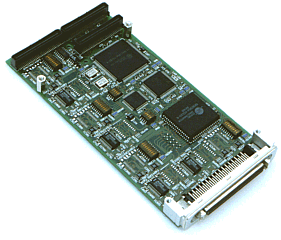
PMC SIO4 and PMC SIO8 PMC Serial Communications Modules
Four or eight channels providing RS232 or RS422/485 (factory option), 16C950 UARTs (high performance version of 16550), RS232 up to 1M baud with an 8 signal interface, RS422/485 up to 12M baud with 4 signal interface, all channels available via front panel SCSI-II style connector and via PMC P4 connector for rear I/O
Key Features
- Conformance to PMC standard IEEE P1386.1/Draft 2.0 4th April 1995
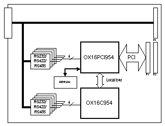
- 32bit PCI single chip quad serial controller. (Oxford Semiconductor OC16PCI954).
- Secondary quad serial controller. (Oxford Semiconductor OC16C954).
- Configuration EEPROM for PCI subsystem, subsystem vendor ID and other configuration information.
- Build options of either RS232 or RS422/485 on a per channel basis.
- All 8 serial channel available via front panel connector and PMC rear I/O.
- RS232 option provides TXD, RXD, CTS, RTS, DSR, DTR, DCD and RI.
- RS422/485 option provides differential TXD, RXD, CTS and RTS.
- Switch selectable full or half duplex operation for RS485.
- RS232 Communications up to 1Mbaud
- RS422/485 Communications up to 12Mbaud
Power Consumption (Typical)
- 5V 350mA
- +12V None
- -12V None
Operating Temperature
- 0°C to 70°C
- -5°C to +85°C special order
- 85% Relative Humidity
Software Support
- Windows 95, 98 (standard and enhanced mode)
- Windows NT (standard and enhanced mode)
- VxWorks (standard mode only at present)
- Other to special order
Front Panel Connector Mapping
A 68-way SCSI II style connector is fitted to the front of the board. An eight way break-out lead (68 way to 8 off 9 pin D-types) is available. This connector supports screw-locks to enable a secure connection to be made.
68 way connector pin
RS232 signal
RS422 signal
D-type pin
0
1
2
3
4
5
6
7
1
9
17
27
35
43
51
61
DCD
RTS+
1
2
10
20
28
36
44
54
62
DSR
RTS-
6
3
11
21
29
37
45
55
63
RXD
TXD+
2
4
12
22
30
38
46
56
64
RTS
TXD-
7
5
13
23
31
39
47
57
65
TXD
RXD+
3
6
14
24
32
40
48
58
66
CTS
RXD-
8
7
15
25
33
41
49
59
67
DTR
CTS+
4
8
16
26
34
42
50
60
68
RI
CTS-
9
18
18
19
19
52
52
53
53
GND
GND
5
This pin out is compatible with the BVM cIO200 used with cPC200 ie the same breakout lead may be used with the front panel or rear panel I/O. With rear panel there are no ground pins. The RS422 pinouts are compatible with the BVM TM3000 RS422 and BVME3500 RS422 pin outs.
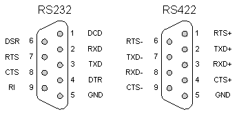
This pin out allows the use of crimp ribbon cable from the 68-way SCSI connector to the D-types if required. The resulting 9 way D-type pin outs are shown below:
Front Panel
A PMC front panel is provided.
LEDs
Surface mount LED's are provided on the underside of the board for transmit and receive for all eight channels.
Switches
The following switches are provided:
Pole |
SW 1 Operation |
|
On |
Off |
|
1 |
50MHz OX16PCI954 clock |
- |
2 |
1.8432MHz OX16PCI954 clock |
- |
3 |
OX16C954 clock same as OX16PCI954 |
- |
4 |
OX16C954 uses UART clock out |
- |
Pole |
SW 2 Operation |
|
On |
Off |
|
1 |
Normal FIFO (16 bytes) |
Enhanced FIFO's (128 bytes) |
2 |
Low power mode select 0 |
|
3 |
Low power mode select 1 |
|
4 |
RI connected to MIO2 |
RI not used |
The low power mode select switches control the RS232 transceiver and select the following:
Select 0 |
Select 1 |
RS232 transceiver operation |
OFF |
OFF |
Always on. |
OFF |
ON |
Auto shutdown mode. |
ON |
OFF |
Controlled by MIO. |
ON |
ON |
Controlled by MIO and auto-shutdown mode. |
In auto-shutdown mode the RS232 transceivers enter a low power mode after 30s on inactivity.
The following switch is provided per channel when RS422/485 buffers are fitted:
Pole |
Operation |
|
On |
Off |
|
1 |
120W termination TXD |
No termination |
2 |
120W termination RXD |
No termination |
3 |
120W termination RTS |
No termination |
4 |
120W termination CTS |
No termination |
5 |
TXD/RXD full duplex |
TXD/RXD half duplex |
6 |
CTS/RTS full duplex |
CTS/RTS half duplex |
7 |
RS485 driver controller by DTR |
Always enable RS485 driver |
8 |
- |
- |


